Fire & Thermal Shock in Concrete Structures: Assessment, Structural Damage, Repair Methodologies and Rehabilitation Solutions for Industrial Facilities
Looking for an Expert in Fire & Thermal Shock Damage Assessment and Structural Rehabilitation?
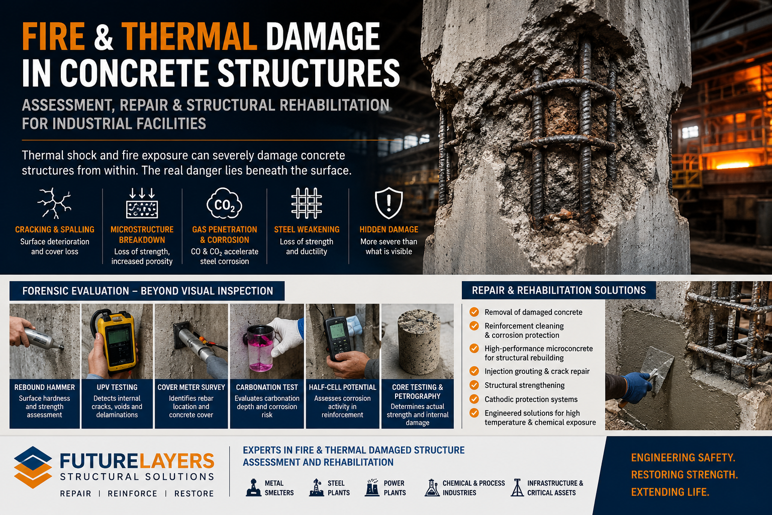
Thermal shock is one of the most underestimated causes of structural deterioration in reinforced concrete structures. While visible cracking, surface scaling, and spalling are often the first signs of distress, the actual damage caused by thermal exposure extends far deeper into the concrete matrix and reinforcing steel.
Industries such as aluminum smelters, steel plants, foundries, power plants, cement plants, chemical processing facilities, refineries, and high-temperature manufacturing units routinely expose reinforced concrete structures to elevated temperatures and sudden thermal fluctuations. Over time, these thermal cycles can significantly reduce structural integrity, durability, and service life.
Futurelayers Structural Solutions specializes in the assessment, diagnosis, repair, strengthening, and rehabilitation of thermally damaged reinforced concrete structures, including facilities exposed to continuous high temperatures, thermal cycling, fire incidents, and industrial process heat.
What Is Thermal Shock in Concrete?
Thermal shock occurs when concrete experiences a rapid temperature change that creates internal stresses exceeding the material’s tensile capacity.
The phenomenon may result from:
- Sudden heating
- Sudden cooling
- Fire exposure
- Furnace operations
- Smelter environments
- Molten metal processing
- Steam exposure
- High-temperature industrial operations
Unlike conventional structural cracking, thermal shock affects the internal microstructure of concrete and can significantly alter its physical and mechanical properties.
How High Temperature Affects Concrete
Concrete is a composite material consisting of cement paste, aggregates, water, and entrapped air.
When subjected to elevated temperatures, multiple deterioration mechanisms occur simultaneously.
Dehydration of Cement Hydration Products
At elevated temperatures, chemically bound water begins to escape from hydrated cement compounds.
This leads to:
- Reduction in cement matrix strength
- Increased porosity
- Loss of cohesion
- Reduction in compressive strength
Differential Thermal Expansion
Aggregates and cement paste expand at different rates.
This creates:
- Internal stresses
- Microcracking
- Loss of aggregate-paste bond
- Surface cracking
Increased Permeability
Thermal damage opens microchannels within the concrete matrix.
This allows:
- Moisture ingress
- Chloride penetration
- Carbon dioxide penetration
- Accelerated reinforcement corrosion
Concrete Spalling
When moisture trapped within concrete rapidly converts to steam, internal pressure develops.
The result may be:
- Explosive spalling
- Cover concrete loss
- Exposure of reinforcement
- Significant reduction in section thickness
Impact of Thermal Shock on Reinforcement Steel
The effects of thermal exposure are not limited to concrete.
Reinforcing steel experiences significant changes when exposed to elevated temperatures.
Potential consequences include:
- Loss of yield strength
- Reduction in ductility
- Permanent metallurgical changes
- Reduced fatigue resistance
- Increased susceptibility to corrosion
Even when steel appears visually unaffected, its mechanical properties may have deteriorated substantially.
This is particularly critical in:
- Smelter structures
- Furnace foundations
- Industrial processing units
- Fire-affected buildings
- Power generation facilities
Why Surface Inspection Alone Is Not Sufficient
One of the most common mistakes in post-fire or thermal shock investigations is relying solely on visual observations.
Surface cracks often represent only a fraction of the actual damage.
The real deterioration frequently occurs deep within the structural member.
A comprehensive forensic investigation is therefore essential.
Advanced Evaluation of Thermally Damaged Concrete Structures
Futurelayers follows a systematic investigation methodology for thermally affected structures.
Visual Condition Assessment
The initial inspection includes:
- Crack mapping
- Spalling assessment
- Distortion evaluation
- Surface discoloration analysis
- Structural distress identification
Rebound Hammer Testing
Used for:
- Surface hardness evaluation
- Comparative strength assessment
- Damage zoning
Ultrasonic Pulse Velocity (UPV) Testing
UPV testing helps identify:
- Internal cracking
- Delamination
- Concrete quality variations
- Damage depth
Cover Meter Survey
Used to determine:
- Reinforcement location
- Concrete cover thickness
- Repair planning requirements
Carbonation Depth Testing
Evaluates:
- Carbon dioxide penetration
- Corrosion risk
- Durability condition
Half-Cell Potential Testing
Assesses:
- Corrosion activity
- Reinforcement condition
Concrete Core Extraction
Core testing provides:
- Actual compressive strength
- Petrographic evaluation
- Damage depth assessment
- Material characterization
Petrographic Analysis
Petrographic studies reveal:
- Microcracking
- Aggregate deterioration
- Thermal decomposition
- Internal matrix damage
This level of investigation is often essential in industrial facilities where structural safety and operational continuity are critical.
Thermal Shock at 70°C and Beyond
Many facility owners assume thermal distress occurs only at extreme temperatures.
In reality, repeated exposure to temperatures around 70°C can initiate deterioration mechanisms over time.
Repeated thermal cycling may result in:
- Shrinkage cracking
- Expansion-related distress
- Bond degradation
- Durability reduction
Industrial environments often expose structures to temperatures well beyond this threshold, accelerating damage progression.
Challenges of Rehabilitation in High-Temperature Industrial Environments
Repairing thermally damaged structures is significantly more complex than conventional concrete repair.
Key challenges include:
Continuous Heat Exposure
Repairs often need to be executed while adjacent equipment remains operational.
Restricted Access
Industrial plants frequently present:
- Congested work zones
- Elevated work areas
- Safety restrictions
Chemical Exposure
Many thermally affected structures are simultaneously exposed to:
- Sulphates
- Acids
- Alkalis
- Industrial chemicals
Production Constraints
Shutdown windows are often limited, requiring carefully planned execution strategies.
Futurelayers has extensive experience managing rehabilitation projects under these demanding conditions.
Structural Rehabilitation Methodology for Thermal Shock Damage
The repair strategy depends on the severity and depth of deterioration.
Step 1: Damage Mapping
The damaged zones are identified and categorized.
Step 2: Removal of Unsound Concrete
All thermally damaged concrete is removed until sound substrate is exposed.
This includes:
- Delaminated concrete
- Cracked concrete
- Carbonated concrete
- Contaminated concrete
Step 3: Reinforcement Treatment
Exposed reinforcement is:
- Cleaned
- Evaluated
- Protected
- Supplemented where necessary
Step 4: Corrosion Protection
Protective systems may include:
- Zinc-rich coatings
- Passivation systems
- Cathodic protection solutions
Step 5: Structural Rebuilding
The damaged section is reconstructed using high-performance repair materials.
Why Microconcrete Is Often the Preferred Repair Material
For heavily damaged structural members, microconcrete frequently becomes the most effective rehabilitation solution.
Advantages include:
- High flowability
- Excellent bond strength
- Controlled shrinkage
- Structural-grade performance
- Dense matrix formation
Microconcrete allows restoration of:
- Columns
- Beams
- Pedestals
- Foundations
- Industrial structures
Futurelayers High-Performance Microconcrete Solutions
Futurelayers Structural Solutions has developed advanced microconcrete systems specifically designed for challenging industrial environments.
These systems are engineered to provide:
- High early strength
- Long-term durability
- Thermal shock resistance
- Chemical resistance
- Low permeability
- Superior structural performance
The objective is not merely to repair damaged concrete but to restore and enhance structural durability under demanding service conditions.
Rehabilitation of Smelter Structures and High-Temperature Industrial Facilities
One of the specialized capabilities of Futurelayers Structural Solutions is the rehabilitation of structures exposed to:
- Aluminum smelters
- Ferroalloy plants
- Steel plants
- Furnace operations
- High-temperature processing units
These structures often experience a combination of:
- Thermal shock
- Corrosion
- Chemical attack
- Mechanical loading
Successful rehabilitation requires multidisciplinary expertise in structural engineering, construction chemicals, corrosion science, and industrial maintenance.
Why Futurelayers Is a Trusted Structural Rehabilitation Partner
Futurelayers provides comprehensive solutions for:
- Fire-Damaged Concrete Repair
- Thermal Shock Damage Assessment
- Structural Condition Evaluation
- Concrete Rehabilitation
- Industrial Structure Repair
- Corrosion Protection
- Microconcrete Rehabilitation
- Injection Grouting
- Structural Strengthening
- Cathodic Protection
- Concrete Durability Enhancement
Our team combines forensic investigation, engineering analysis, construction chemical expertise, and specialized execution capabilities to restore critical infrastructure safely and effectively.
Frequently Asked Questions
Can concrete recover after thermal shock?
Minor damage may be repairable, but significant thermal exposure often causes permanent changes to the concrete microstructure. Detailed assessment is required before determining rehabilitation measures.
How is thermally damaged concrete evaluated?
A combination of visual inspection, UPV testing, rebound hammer testing, carbonation testing, cover meter surveys, petrographic analysis, and core testing is typically required.
Is microconcrete suitable for thermally damaged structures?
Yes. High-performance microconcrete is often used to restore structural sections after removal of damaged concrete.
Can reinforcement lose strength due to heat exposure?
Yes. Elevated temperatures can permanently reduce steel strength and ductility depending on the temperature and duration of exposure.
Who should assess fire-affected or thermally damaged concrete structures?
Assessment should be performed by experienced structural rehabilitation specialists with expertise in forensic investigation, concrete technology, durability engineering, and repair methodologies.
Contact Futurelayers Structural Solutions
If your facility is experiencing thermal damage, fire-related concrete deterioration, high-temperature exposure, reinforcement corrosion, spalling, cracking, or durability concerns, Futurelayers can provide comprehensive assessment, repair design, material selection, rehabilitation planning, and execution support.
From smelter units and power plants to industrial manufacturing facilities and critical infrastructure, Futurelayers delivers engineered solutions for restoring structural integrity, durability, and long-term performance.
Application Methodology
Application Methodology for Rehabilitation of Fire and Thermally Damaged Concrete Structures
The rehabilitation of fire-affected and thermally distressed reinforced concrete structures requires a systematic engineering approach. The methodology adopted by Futurelayers Structural Solutions focuses on restoring structural integrity, durability, and long-term performance while ensuring compatibility with the existing structure.
1. Condition Assessment and Damage Mapping
Before commencing repair works, a detailed structural assessment shall be carried out to determine the extent of thermal damage.
Activities include:
-
Visual inspection and crack mapping
-
Delamination survey
-
Rebound hammer testing
-
Ultrasonic Pulse Velocity (UPV) testing
-
Cover meter survey
-
Carbonation depth testing
-
Half-cell potential testing
-
Petrographic analysis
-
Concrete core extraction and testing
-
Reinforcement condition assessment
The outcome of this investigation helps classify areas as:
2. Isolation and Safety Measures
Prior to rehabilitation:
-
Barricade work areas
-
Isolate adjacent operational equipment
-
Install temporary supports where required
-
Ensure compliance with plant safety protocols
-
Obtain work permits and shutdown clearances
Particular attention is required in smelters, power plants, and high-temperature industrial environments.
3. Removal of Thermally Damaged Concrete
All unsound concrete shall be removed using suitable methods such as:
-
Light chipping
-
Hydro-demolition
-
Mechanical scarification
-
Needle scaling
Concrete removal shall continue until sound substrate is achieved.
Removal criteria include:
-
Delaminated concrete
-
Carbonated concrete
-
Cracked concrete
-
Spalled concrete
-
Heat-damaged concrete
-
Contaminated concrete
4. Surface Preparation
The exposed substrate shall be prepared to achieve a clean and mechanically sound surface.
Surface preparation includes:
-
Removal of dust and debris
-
Oil and grease cleaning
-
Abrasive blasting where required
-
High-pressure air cleaning
-
High-pressure water jetting
The final surface shall be free from contaminants that may affect bond strength.
5. Reinforcement Treatment
Exposed reinforcement shall be thoroughly inspected.
Activities include:
-
Rust removal by grit blasting or mechanical cleaning
-
Measurement of steel section loss
-
Replacement of severely deteriorated bars
-
Installation of supplementary reinforcement where required
6. Corrosion Protection System
Following cleaning, reinforcement shall be protected using appropriate corrosion mitigation measures.
Depending upon project requirements:
-
Zinc-rich coatings
-
Cementitious passivation coatings
-
Migratory corrosion inhibitors
-
Cathodic protection systems
may be employed.
7. Bond Coat Application
A high-performance bonding agent shall be applied to improve adhesion between existing concrete and repair material.
Suitable systems include:
Selection depends upon environmental and thermal exposure conditions.
8. Microconcrete Placement
The damaged section shall be reinstated using high-performance structural microconcrete.
Futurelayers recommends microconcrete with:
The microconcrete shall be poured into properly sealed formwork to ensure complete filling of cavities.
Applications include:
9. Crack Repair and Injection Grouting
Where cracks are identified, appropriate repair systems shall be employed.
Structural Cracks
Repair using:
Active Water Leakage Cracks
Repair using:
Non-Structural Cracks
Repair using:
10. Structural Strengthening (If Required)
Where structural analysis indicates loss of capacity, strengthening measures may include:
11. Protective Coating Application
Following rehabilitation, the repaired surfaces shall be protected using suitable protective systems.
Depending upon exposure conditions:
-
Anti-carbonation coatings
-
Epoxy coatings
-
PU coatings
-
Chemical-resistant coatings
-
Thermal-resistant coatings
may be applied.
12. Quality Control and Testing
Post-repair quality assurance shall include:
Acceptance criteria shall be established based on project specifications and structural requirements.
13. Long-Term Monitoring
Futurelayers recommends periodic monitoring of rehabilitated structures through:
-
Annual inspections
-
Corrosion monitoring
-
Crack monitoring
-
Durability assessments
-
Thermal exposure reviews
This ensures continued structural performance and extended service life.
Futurelayers Expertise in Fire and Thermal Damage Rehabilitation
Futurelayers Structural Solutions provides specialized rehabilitation services for:
-
Fire-Damaged Concrete Structures
-
Thermally Distressed RCC Structures
-
Aluminum Smelters
-
Steel Plants
-
Ferroalloy Plants
-
Cement Plants
-
Refineries
-
Power Plants
-
Industrial Processing Units
Our expertise encompasses forensic investigation, structural assessment, repair design, microconcrete rehabilitation, corrosion protection, cathodic protection, injection grouting, and structural strengthening to restore critical infrastructure exposed to extreme thermal and chemical environments.
Specifications
Technical Specification for Rehabilitation of Fire and Thermally Damaged Reinforced Concrete Structures
1. Scope of Work
The work shall comprise assessment, preparation, repair, rehabilitation, strengthening, and protection of reinforced concrete structures affected by fire exposure, thermal shock, elevated temperatures, industrial process heat, and associated deterioration mechanisms.
The scope shall include:
-
Condition assessment and damage mapping
-
Removal of thermally deteriorated concrete
-
Reinforcement treatment and protection
-
Structural repairs using microconcrete and repair mortars
-
Crack repair through injection grouting
-
Structural strengthening where required
-
Protective coating application
-
Quality assurance and testing
The objective is to restore structural integrity, durability, serviceability, and design performance of the affected structure.
2. Reference Standards
The repair and rehabilitation works shall comply with the latest editions of:
-
IS 456 – Plain and Reinforced Concrete Code
-
IS 13311 – Non-Destructive Testing of Concrete
-
IS 516 – Methods of Tests for Strength of Concrete
-
IRC SP 40 – Guidelines for Repair and Rehabilitation of Concrete Bridges
-
ACI 546R – Concrete Repair Guide
-
ACI 562 – Assessment, Repair and Rehabilitation of Existing Concrete Structures
-
EN 1504 – Products and Systems for Repair and Protection of Concrete Structures
-
ASTM C597 – Ultrasonic Pulse Velocity
-
ASTM C805 – Rebound Hammer Testing
3. Investigation and Assessment
Prior to commencement of repairs, a comprehensive assessment shall be carried out.
The investigation shall include:
Visual Inspection
Non-Destructive Testing
Destructive Testing
The consultant shall identify the extent and depth of thermal damage and categorize repair zones.
4. Concrete Removal
All damaged, loose, cracked, delaminated, carbonated, thermally affected, and unsound concrete shall be removed.
Removal methods may include:
-
Mechanical chipping
-
Hydro-demolition
-
Scarification
-
Needle scaling
Concrete removal shall continue until sound concrete is exposed.
The edges of repair zones shall be cut perpendicular to the surface to a minimum depth of 10 mm.
5. Surface Preparation
The prepared substrate shall be:
Surface preparation may be carried out using:
Prepared surfaces shall be inspected prior to repair application.
6. Reinforcement Treatment
All exposed reinforcement shall be inspected.
The reinforcement shall be cleaned to near white metal finish using:
-
Grit blasting
-
Mechanical wire brushing
Where reinforcement section loss exceeds 20%, replacement or supplementary reinforcement shall be provided as approved by the structural consultant.
7. Reinforcement Protection
Following cleaning, reinforcement shall receive corrosion protection treatment.
Corrosion protection material shall:
-
Be cementitious or epoxy-based
-
Contain active corrosion inhibitors
-
Be compatible with repair materials
-
Provide alkaline protection
Minimum coating thickness shall be as per manufacturer’s recommendations.
8. Bonding System
Prior to placement of repair material, a bonding system shall be applied.
The bonding system shall possess:
-
Minimum bond strength ≥ 2.0 MPa
-
Excellent compatibility with existing concrete
-
Resistance to thermal cycling
-
Resistance to moisture ingress
Bonding materials may include:
9. Structural Repair Material – Microconcrete
Repair material shall be free-flowing, non-shrink, structural-grade microconcrete.
Minimum Performance Requirements
| Property |
Requirement |
| Compressive Strength (1 Day) |
≥ 15 MPa |
| Compressive Strength (7 Days) |
≥ 35 MPa |
| Compressive Strength (28 Days) |
≥ 60 MPa |
| Flexural Strength |
≥ 8 MPa |
| Bond Strength |
≥ 2.0 MPa |
| Drying Shrinkage |
< 500 Microstrain |
| Chloride Content |
Nil |
| Flowability |
Self Compacting |
| Thermal Shock Resistance |
Excellent |
| Sulphate Resistance |
Excellent |
| Chemical Resistance |
Excellent |
The material shall be suitable for heavily reinforced sections and industrial environments.
10. Crack Repair
Structural Cracks
Structural cracks wider than 0.2 mm shall be repaired using low-viscosity epoxy injection systems.
Epoxy injection material shall possess:
Active Leakage Cracks
Active water-bearing cracks shall be repaired using hydrophilic or hydrophobic polyurethane injection systems.
11. Structural Strengthening
Where structural evaluation indicates insufficient load-carrying capacity, strengthening systems may include:
-
CFRP wrapping
-
Steel plate bonding
-
RC jacketing
-
Section enlargement
-
External post-tensioning
The strengthening design shall be approved by the structural consultant.
12. Protective Coating System
Following repairs, exposed surfaces shall receive a protective coating system.
Depending upon service conditions, the coating may consist of:
Minimum dry film thickness shall be as recommended by the coating manufacturer.
13. Quality Control Requirements
The contractor shall maintain records of all quality control activities.
Testing Requirements
-
Rebound Hammer Testing
-
UPV Testing
-
Pull-Off Bond Strength Testing
-
Flow Test of Microconcrete
-
Cube Strength Testing
-
Coating Thickness Measurement
Acceptance Criteria
Pull-Off Strength
Compressive Strength
Visual Inspection
-
No cracks
-
No honeycombs
-
No voids
-
Uniform finish
14. Health, Safety and Environmental Requirements
The contractor shall comply with all applicable safety regulations.
Special precautions shall be taken in:
Appropriate PPE, permit systems, scaffolding, and confined space procedures shall be implemented.
15. Measurement and Payment
Measurement shall be carried out based on:
-
Cubic meter (m³) for concrete repair
-
Square meter (m²) for surface treatment and coating
-
Running meter (RM) for crack injection
-
Kilogram (kg) for reinforcement replacement
Payment shall include all materials, labour, equipment, testing, scaffolding, curing, quality control, and incidental works necessary to complete the rehabilitation.
Futurelayers Structural Solutions
Futurelayers specializes in:
-
Fire-Damaged Concrete Repair
-
Thermal Shock Damage Rehabilitation
-
Industrial Structure Rehabilitation
-
Smelter Structure Repair
-
Structural Strengthening
-
Microconcrete Rehabilitation
-
Injection Grouting
-
Corrosion Protection
-
Cathodic Protection Systems
-
Concrete Durability Enhancement
Our rehabilitation systems are engineered to restore structural integrity and long-term durability in demanding industrial and high-temperature operating environments.
This specification is suitable for inclusion in tender documents, method statements, repair proposals, consultant reports, and technical submissions for industrial plants, smelters, power plants, refineries, and fire-damaged RCC structures. Contact Futurelayers for customised specification.